Electrical Wiring Diagram Symbols Australia Wiring Digital and Schematic
This solution provides 26 libraries which contain 926 electrical symbols from electrical engineering: Analog and Digital Logic, Composite Assemblies, Delay Elements, Electrical Circuits, Electron Tubes, IGFET, Inductors, Integrated Circuit, Lamps, Acoustics, Readouts, Logic Gate Diagram, MOSFET, Maintenance, Power Sources, Qualifying, Resistors,.
PHC Facility Management Electricity Definition, Units, Sources, Alternating Current, Codes
legend of symbols client: architect: project: title: checked: approved: date: rev: scale @ a0: do not scale project number: drawing no: drawn: drawing created in revit. powcom powcom sheet status no revision by chk date electrical services note: do not scale from drawings. verify all dimensions on site before commencing work. copying or the.

Pearl Scheme Common Electrical Wiring Symbols For Architecture Arm64
As the name suggests, Australian Standard Electrical Schematic Symbols are the result of an international standard. This standard was designed to ensure that all electrical systems are created using the same symbols, regardless of the country of origin. This means that engineers from around the world can understand and use the same schematic.

Electrical drawing symbols Drawing Standards Pinterest Drawings, Zen and Australia
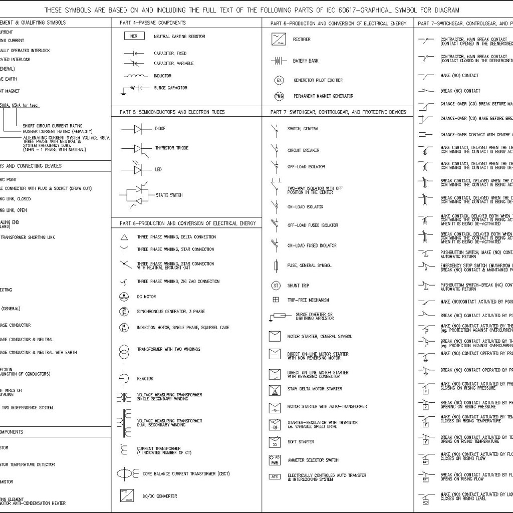
Description Attached Files CAD blocks of Electrical Symbols AS-NZS. Common general electrical symbols as used in Australia and New Zealand. AutoCAD 2010 DWG format. Free to download. By Dave. Preview of CAD file - ElectricalSymbols-AS-NZS-CIRCUIT-BREAKER-SWITCHES-CONTACTS.dwg Preview of CAD file - ElectricalSymbols-AS-NZS-STARTERS-METERS.dwg

Electrical Floor Plan Symbols Australia (see description) YouTube
Australian Standard Electrical Circuit Symbols (ASECS) are an integral part of electrical engineering in Australia, providing the necessary information to identify the components, layout and control systems for any given electrical circuit.. House Electrical Plan Software Diagram Symbols. Electrical Symbols Images Browse 1 132 150.

Electrical Symbology Electrical symbols, Blueprint symbols, Electrical plan symbols
Electrical Plan Symbols Design & Documentation > Construction Documentation Every engineering office uses their own set of electrical symbols; however, the symbols below are fairly common across many offices. Refer to the legend sheet in your set of plans for special symbols used in a particular set. Article Contents Power Symbols Lighting Symbols

Ross Wiring Wiring Diagram Symbols Australia 2019 Pdf Free
The floor plan shows the layout of the building for rooms, windows, doors, appliances, etc. It includes details about the building such as: position of appliances. The floor plan may also indicate positions of electrical fittings such as: cable routes. In order to correctly position components this information must be referred to when wiring a.

Ansi Standard Electrical Schematic Symbols Wiring Technology
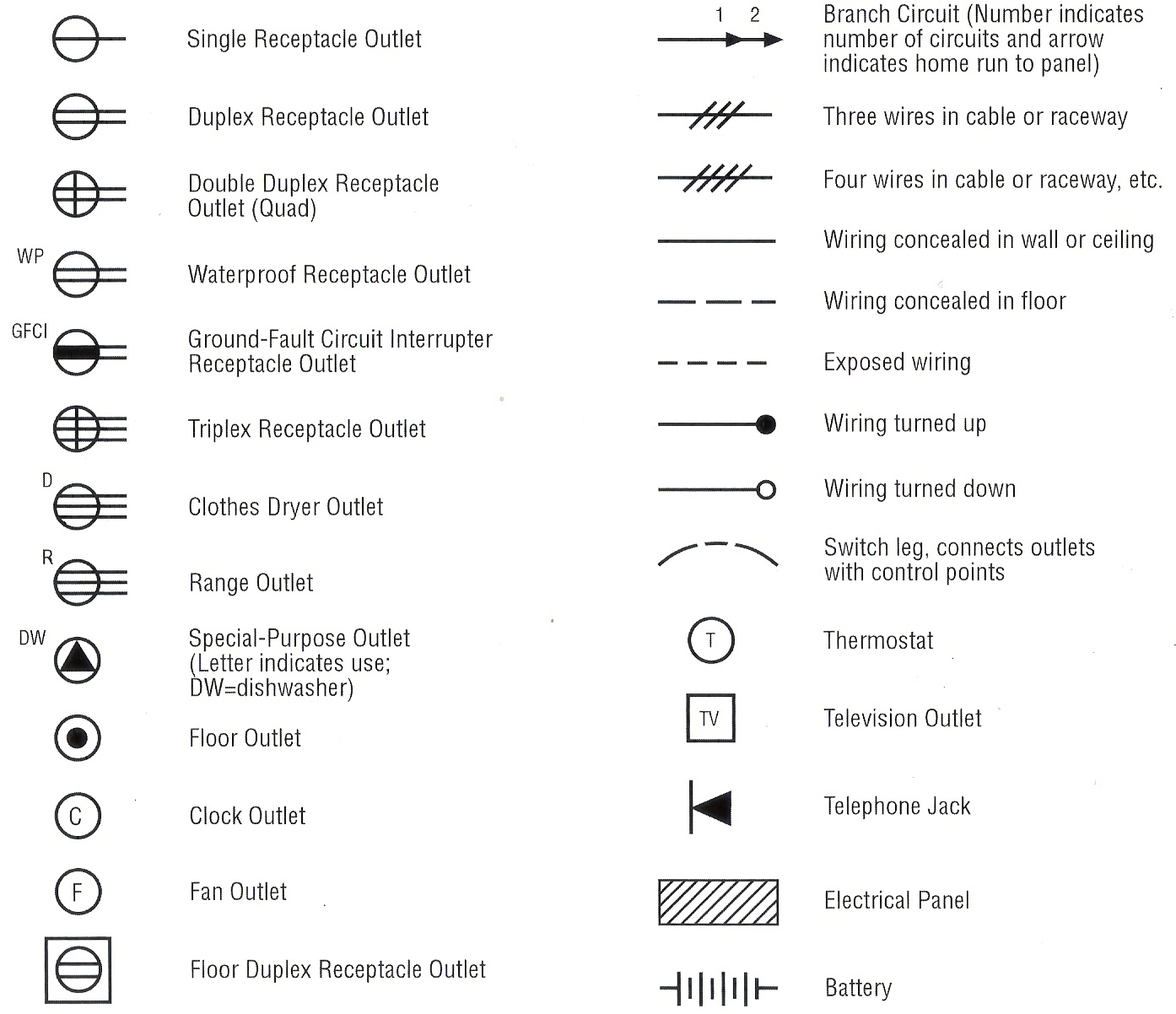
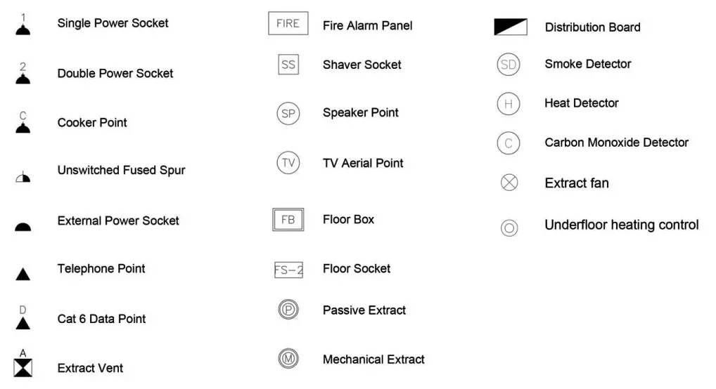
Electrical components are also represented on floor plans using Australian Standard symbols. (AS 1102.111:1997 Graphical Symbols for electrotechnology documentation Part 111: Architectural and topographical plans and diagrams.) A sample of these symbols is shown below: Select a title to see related symbols Switches Switch - general

Milly Cole Residential Electrical Plan Symbols Pdf
There are standard symbols used in electrical plans. The dotted line represents the wire that connects the light to the switch. In the plan top the left No 1 is the light fitting, 2 the switch and 3 the power point. An electrical plan always has a legend so the builder and electrician know what each symbol on the plan represents.

Wiring Diagram Symbols Australia 2019 Youtube Orla Wiring
Online manuals and video tutorials only available via Haynes direct. Search hundreds of online and print manuals and get the right one from Haynes.

Ellen Scheme Common House Wiring Diagram Symbols Charter
The Electrical Symbols provided are based on a 10mm grid placement and should not be dropped or nested. Line weights for Schematic Interconnection are as follows: - Power Cabling = Weight 4 Control Cabling = Weight 2 Earth and Neutral Cabling = Weight 0
Electrical drawing symbols in autocad jesdesk
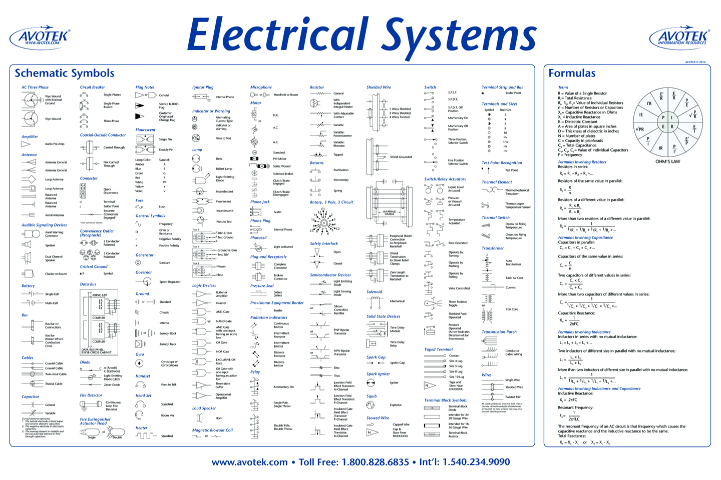
Resources Electrical drawings Symbols Like architectural drawings, standard graphical symbols are used on electrical drawings to represent specific items such as: switches conductors relays lights, etc. Using standard symbols ensures that anyone who know the standards can interpret the drawings correctly.
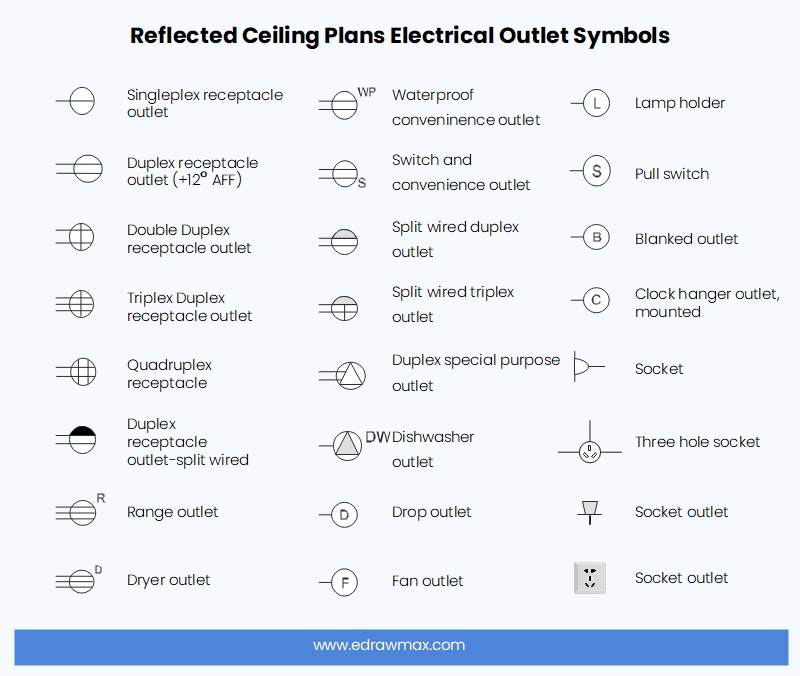
Reflected Ceiling Plan Symbols and Meanings EdrawMax Online
Electrical Plan symbols? by Bam Page 1 of 1 8 replies Bam 23/08/2009 I want to work on my electrical plan but I dont know what symbols to use Is there a standard set of symbols that builders use? i.e. this means powerpoint, this means downlight, this means fan.. etc?

Infographic of blueprint symbols Blueprint symbols, Floor plan symbols, Architecture symbols
Australian / New Zealand electrical symbols for drafting. Circuit breakers, switches and contacts. A free AutoCAD block DWG file download. A preview of the DWG file download. Subscribe to our Youtube Channel

Residential Electrical Wiring Diagram Symbols
July 15, 2023 by Ana Oshi Australian Standard Circuit Diagram Symbols are essential in helping quickly and accurately interpret the function of an electrical system. Without these symbols, electricians would be left guessing what the wiring means.
Floor Plan Symbols and Abbreviations to Read Floor Plans Foyr
DIM - Dimmer. DGPO - Double General Power Outlet. ECU - Evaporative Cooling Unit. ELCB - Earth Leakage Circuit Breaker. GPO - General Power Outlet. IP - Ingess Protection. Range from a basic IP 30 (standard outlet) to IP67 (fittings to withstand total immersion in water) JB - Junction Box. LV - Low Voltage.
